


5 Phase Open Loop Stepper Drive 5R42


Product Introduction


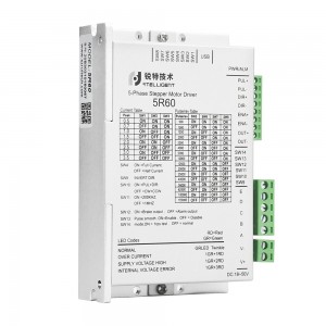
Connection

Features
• Power supply : 24 - 36VDC
• Output current: DIP switch setting, 8-speed selection, maximum 2.2A (peak)
• Current Control: New Pentagon Connection SVPWM Algorithm and PID Control
• Subdivision setting: DIP switch setting, 16 options
• Matching motor: Five-phase stepper motor with new pentagon connection
• System self-test: The motor parameters are detected during the power-on initialization of the driver, and the current control gain is optimized according to the voltage conditions.
• Control mode: Pulse & direction; double pulse mode
• Noise filter: software setting 1MHz~100KHz
• Instruction smoothing: Software setting range 1~512
• Idle current: DIP switch selection, after the motor stops running for 2 seconds, the idle current can be set to 50% or 100%, and the software can be set from 1 to 100%.
• Alarm output: 1 channel optically isolated output port, default is alarm output, can be reused as brake control
• Communication interface: USB
Current Setting
|
Phase current peak A |
SW1 |
SW2 |
SW3 |
|
0.3 |
ON |
ON |
ON |
|
0.5 |
OFF |
ON |
ON |
|
0.7 |
ON |
OFF |
ON |
|
1.0 |
OFF |
OFF |
ON |
|
1.3 |
ON |
ON |
OFF |
|
1.6 |
OFF |
ON |
OFF |
|
1.9 |
ON |
OFF |
OFF |
|
2.2 |
OFF |
OFF |
OFF |
Micro-stepping Setting
|
Pulse/rev |
SW5 |
SW6 |
SW7 |
SW8 |
|
500 |
ON |
ON |
ON |
ON |
|
1000 |
OFF |
ON |
ON |
ON |
|
1250 |
ON |
OFF |
ON |
ON |
|
2000 |
OFF |
OFF |
ON |
ON |
|
2500 |
ON |
ON |
OFF |
ON |
|
4000 |
OFF |
ON |
OFF |
ON |
|
5000 |
ON |
OFF |
OFF |
ON |
|
10000 |
OFF |
OFF |
OFF |
ON |
|
12500 |
ON |
ON |
ON |
OFF |
|
20000 |
OFF |
ON |
ON |
OFF |
|
25000 |
ON |
OFF |
ON |
OFF |
|
40000 |
OFF |
OFF |
ON |
OFF |
|
50000 |
ON |
ON |
OFF |
OFF |
|
62500 |
OFF |
ON |
OFF |
OFF |
|
100000 |
ON |
OFF |
OFF |
OFF |
|
125000 |
OFF |
OFF |
OFF |
OFF |
| When 5, 6, 7 and 8 are all ON, any micro-stepping can be changed through debugging software. | ||||
-
 Rtelligent 5R42 User Manual