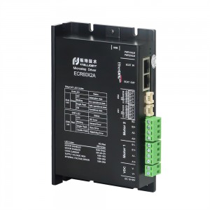


Modbus TCP Open loop Stepper Drive EPR60


Product Introduction


Connection

Features
• Power supply: 18 - 50VDC.
• Output current: Maximum 6.0A (Peak).
• Current control: SVPWM algorithm and PID control.
• Revolution setting: 200 ~ 4,294,967,295.
• Matched motor: 2 phase / 3 phase stepper motor.
• System self-test: Detect motor parameters during drive power-on initialization and optimize current control gain based on voltage conditions.
• Instruction smoothing: Trapezoidal curve optimization, 1~512 levels can be set.
• Input port|: There are 6 input ports, of which 2 can receive differential signals of 5V~24V level for orthogonal encoder signal access (Applicable to EPT60), and 4 receive 5V/24V signal-ended signal.
• Output port: 2 photoelectric isolation output, the maximum withstand voltage is 30V, and the maximum sink current or source current is 100mA.
• Communication interface: 1 RJ45 network port for bus communication, 1 USB port for firmware upgrade.
• Motion control: Acceleration, deceleration, speed,stroke can be set, homing function.
Function Setting
|
Pin |
Name |
Description |
|
1 |
EXT5V |
The drive outputs a 5V power supply for external signals.Maximum load: 150mA. It can be used for power supply of optical encoder. |
|
2 |
EXTGND |
|
|
3 |
IN6+/EA+ |
Differential input signal interface, 5V~24V compatible. In open-loop external pulse mode, it can receive direction. In closed-loop mode, this port is used to receive quadrature encoder A-phase signal. Note:The closed-loop mode is only applicable to the EPT60. |
|
4 |
IN6-/EA- |
|
|
5 |
IN5+/EB+ |
Differential input signal interface, 5V~24V compatible. In open-loop external pulse mode, it can receive direction. In closed-loop mode, this port is used to receive quadrature encoder B-phase signal. Note:The closed-loop mode is only applicable to the EPT60. |
|
6 |
IN5-/EB- |
|
|
7 |
IN3 |
Universal input port 3, default to receive 24V/0V level signal. |
|
8 |
IN4 |
Universal input port 4, default to receive 24V/0V level signal. |
|
9 |
IN1 |
Universal input port 1, default to receive 24V/0V level signal. |
|
10 |
IN2 |
Universal input port 2, default to receive 24V/0V level signal. |
|
11 |
COM24V |
External IO signal power supply 24V positive. |
|
12,14 |
COM0V |
Internal power supply output GND. |
|
13 |
COM5V |
External IO signal power supply 5V positive. |
|
15 |
OUT2 |
Output port 2, open collector, output current capability up to 100mA. |
|
16 |
OUT1 |
Output port 1, open collector, output current capability up to 30mA. |
IP Setting
IP setting address format: IPADD0. IPADD1. IPADD2. IPADD3
Default: IPADD0=192, IPADD1=168, IPADD2=0
IPADD3 = (S1*10)+S2+10
-
 Rtelligent EP Series User Manual